History
The Beginnings of Electron Beam Technology
When J.J. Thomson first identified the electron as a particle of matter with a negative charge during his work with cathode rays at the University of Cambridge at the end of the 19th century, no one could have imagined that this term would become one of the most widely used in science.
Similarly, its discoverers would certainly never have dreamed how its targeted application would change everyday life to such an extent. Entire industries, such as electronics and microelectronics, bear his name.
Neither computers nor modern communication or the internet would be conceivable without the targeted use of the properties of the electron. But the electron is also very useful as a tool. This is particularly true for accelerated electrons that are focused into a beam. Electrons scan surfaces and provide optical information in the nanometer range, which has advanced science enormously over the last 80 years. In the past, electron beams were also used to generate images. Beyond that, electron beams are also used to bond different metals together, to harden surfaces and to modify plastics.

Figure 1: Family tree of electron beam technologies (from Siegfried S. Schultz, 1-2ebeam2002- International Conference on High-Power Electron Beam Technology - October 27- 29, 2002 - Paper 11)
Electron beams can also be used to efficiently melt and clean refractory metals such as titanium, tungsten and tantalum. Or metals and ceramics can be deposited as functional layers on a wide variety of substrates by vaporization. This article will take a closer look at the latter applications in particular - in conjunction with the work of Manfred von Ardenne in Dresden. Even though Marcello von Pirani had already patented the melting of refractory metals (in this case tantalum) using focused cathode rays in 1905, these findings had no useful effect at the time. This was due to the fact that neither effective high-vacuum pumps nor high-performance electron beam systems were available for industrial use at the time. This required extensive developments in electron optics to shape the electron beam in the 1920s and 1930s. These were driven forward by the development of transmission electron microscopy by Ernst Ruska, Max Knoll and Manfred von Ardenne.
At the same time, the applications of X-rays and the discovery of cosmic rays and the associated desire for experiments with high-energy radiation also awakened the desire for high-energy energy sources. In 1929, van de Graff achieved acceleration voltages of 1.5 MeV with his electrostatic band generator named after him. Manfred von Ardenne also used a generator of this type for experiments on neutrons in his former laboratory for electron physics in Berlin-Lichterfelde. The limiting element in thermal emission was still the space charge in front of the cathode, which prevented emission currents above 1 mA. It was not until 1939 that John Pierce - in conjunction with the 3-electron system described by Rogowski in 1926 - showed a way to influence the field geometry by means of conical electrode geometries in such a way that significant electron emission was possible even with a large space charge.
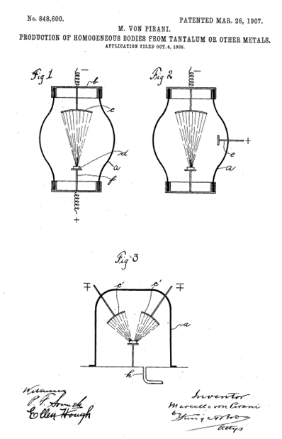
Figure 3: Schematic diagram of a Pierce cathode. The conical electrode shape influences the field geometry in such a way that electron emission can also take place in the space charge range.
Figure 2: US patent by Marcello von Pirani for melting refractory metals
The development of electron beam technology at VON ARDENNE
At the end of the Second World War, all the tools needed to start electron beam metallurgy were known. But it was not until 20 years later that industrial solutions for electron beam melting, evaporation and welding began to establish themselves.
In 1950, electron beam welding was first discovered more or less by chance in the electron microscope laboratory at Zeiss. K.H. Steigerwald then described the drilling of small holes and metalworking as possible applications of the electron beam. Already in 1938, Manfred von Ardenne had described this in a patent, together with von Borris and Ruska. He assumed that micromachining should be possible using a beam of charged particles.
In the 1950s, the focus on the development of space travel and nuclear research led to significant progress in this field.
High-purity metals were needed for this, which required melting processes under extreme vacuum conditions. Arc and induction furnaces reached their limits. During this time, the first powerful electron beam guns were developed, which initially resembled electron microscopes.
However, the first axial EB guns still suffered from various problems. For example, the deposition of the vapor produced during melting quickly led to short circuits on the insulators. A decisive improvement was achieved here when it was realized that the beam diameter could be reduced to such an extent that the outlet opening could be used as a pressure stage to protect the insulators from the metal vapor.
Today's high-performance electron emitters have several of these water-cooled pressure stages.
In conjunction with separate evacuation systems, they protect the beam generation chamber on the vacuum side as far as possible from the harsh conditions in the melting or evaporation area. A further increase in reliability and performance was achieved by using indirectly heated tungsten emitters. The actual large-area cathode is heated by the electron bombardment from a filamentary tungsten emitter on the back. This leads to an easily controllable and stable emission temperature.
From the very beginning, the space charge in front of the cathode was used as an emission-limiting factor. This ensured the necessary stability of the beam power and beam quality against fluctuations in the emission temperature or ageing of the cathodes.
First generation of electron beam guns for melting: powerful but bulky
On this basis, the first pilot-scale electron beam multi-chamber furnace with a beam power of 45 kW for melting steel was developed at the Manfred von Ardenne Research Institute (IvA) back in 1959. The strong demand from the metallurgical industry led to the development of much more powerful electron beam guns. Thus, by the mid-1960s, electron beam guns with a beam power of 1200 kW were already being produced at the IvA for metallurgical purposes.
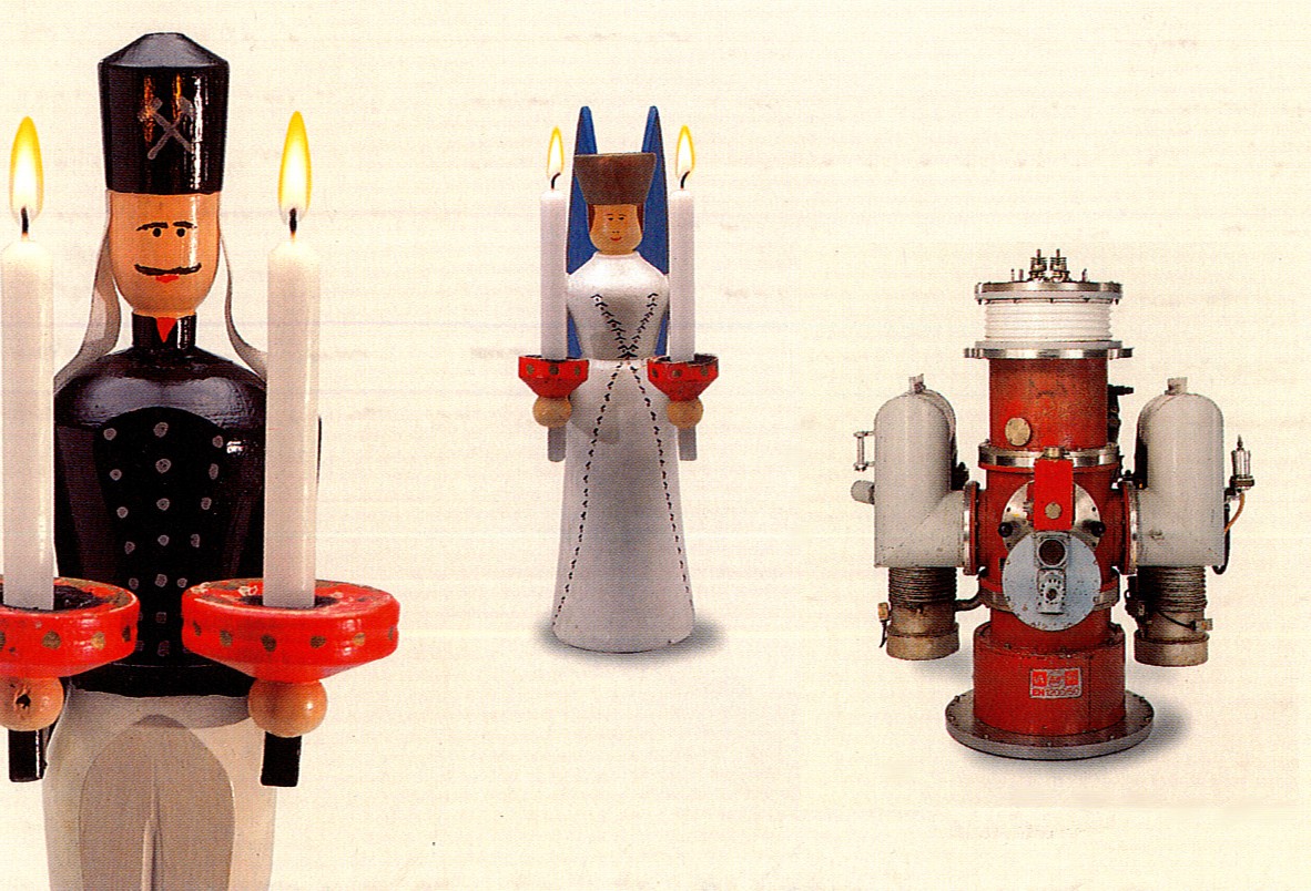
Electron beam guns of this first generation still had a rather bulky design due to their high-voltage potential, directly water-cooled cathode systems and the required insulators. This was necessary because the thermal stability of the cathode system is of great importance for the beam quality and the heat had to be dissipated in this way, particularly in the case of the high-power guns of 1.2 MW. In addition, at that time only oil diffusion pumps were available for the required high vacuum generation, which could be mounted via angled pipe sections. In conjunction with the dominant design of the isolators, these first-generation electron beam guns were also affectionately known as Christmas angels. (see image)
Improvements and further development: the second generation of electron beam guns
Despite the disadvantages, these guns used for melting refractory metals and for evaporating aluminum were very robust with their power classes between 60 kW and 1200 kW. Some of them are still in use today.
The increase in the range of applications, but also requirements for different installation positions and simplification of maintenance led to the development of the 2nd generation of electron beam guns with several fundamental changes described below.
By changing the electrical potentials in the cathode heating system, the heating power could be reduced to a third. As a result, water cooling was no longer necessary and the cathode system, which had been drastically reduced in size and weight, could now disappear into the gun head, which was at ground potential.
Another important innovation concerned the power control. While the first-generation guns were still controlled by changing the accelerating voltage, the position of the anode could now be shifted by means of an actuator and thus also the beam current due to the variable distance between the cathode and anode.
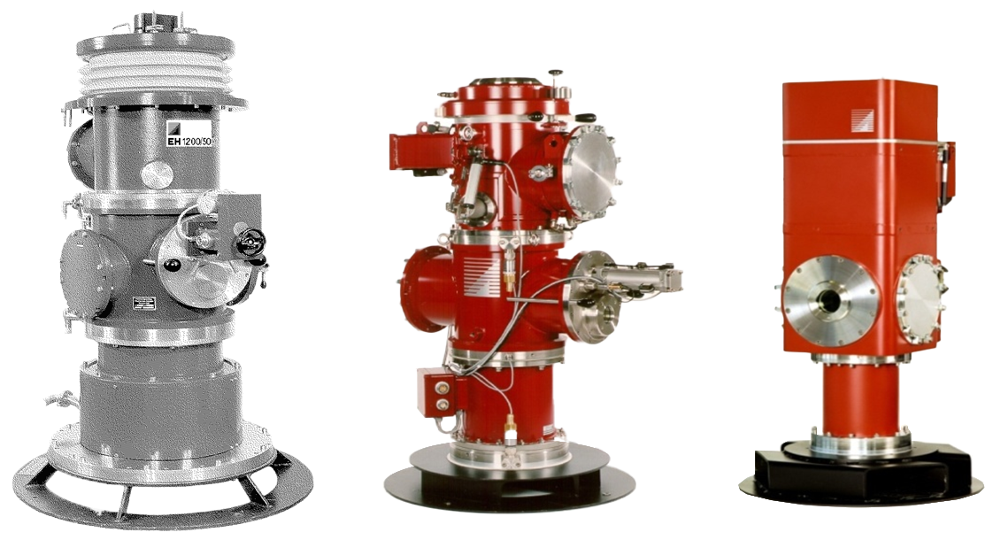
Figure 5: First, second and current generation of electron beam guns
As a result, both the accelerating voltage and the cathode temperature could be kept constant with this solution, known as a Vario Anode. It also reduced the influence of the power control on the electron-optical parameters. With this measure, the high-voltage insulation could be moved to the interior and the outer shell of the gun was completely at ground potential. This was a significant step forward in terms of safety and accessibility. A further significant increase in reliability and operational safety was achieved by using a magnetically gas-focused electron beam. By measuring the temperature in the flow resistance, it was now possible to optimize and stabilize the beam focusing in the area of the flow resistances. The development of the current, even slimmer-looking generation took place at the beginning of the 1990s. Extensive experience from the numerous 2nd generation electron beam guns used in industry was taken into account. A fundamental innovation concerns the beam generation.
With the patented principle of the Vario Cathode, the electron beam power is now adjusted by changing the distance between the cathode and a fixed anode. This was made possible by moving the high-voltage insulator completely into the vacuum and thus significantly reducing the size. Due to the principle of the Vario Cathode, the acceleration voltage and electron-optical geometry remain the same over the entire power range. This results in a much more constant and finely focusable beam quality over the entire power range, as the lens currents no longer have to be adapted to the beam power to the extent originally required. As a result, stable and reproducible beam operation across the entire power range was possible for the first time, which is very important for various applications. A new cathode system design has also been introduced with the movement device for the cathode at high voltage potential.
In conjunction with the cathode arrangement, which operates in space-charge mode, the design has been simplified to such an extent that the plugged-in cathode assembly can be easily replaced during maintenance by means of a quick-change system and no further adjustment of the cathode position is required. This design has been continuously optimized in recent years, resulting in a tried-and-tested industrial solution with a very long service life depending on the process.
Recent developments
In the last 10-15 years, the focus in the further development of the electron beam system has increasingly shifted towards components for high-voltage generation and beam guidance. In particular, the development of powerful medium-frequency power supplies with fast-switching transistors has led to significant progress in the suppression of high-voltage flashovers.
The use of new materials in the beam deflection system and new concepts for the beam guidance software and control hardware also made it possible to increase the deflection frequencies even at large deflection angles. This also gave the operator many simple options for influencing the beam distribution.
Both the flashover cut-off and the increase in deflection frequency play a decisive role in current applications of electron beam technologies. For example, highly productive solutions for the evaporation of silicon oxide for barrier layers on transparent packaging films have been developed for coating applications, which are intended to replace the aluminum-based barrier layers that have mainly been used to date and are difficult to recycle. Due to the material, the evaporation of the silicon oxide takes place sublimating, i.e. without prior melting of the material.
Short-term jet interruptions or inhomogeneities in the solid evaporation material therefore lead to a faster interruption of evaporation than in the thermally slower reacting molten state. At the same time, the film to be coated is transported at speeds of up to 20 m/s. This means that if the electron beam is exposed for one millisecond, for example, the effect can extend to a strip length of up to two centimeters. On the generator side, the exposure time can now be limited to less than 300 µs.
There are similarly high requirements for current coating applications in the battery sector, where a metallized plastic film is to replace metallic electrodes in lithium-ion batteries in the future. High demands on precision, stability and repeatability also play a role in other applications. Here, the electron beam is used as an energy source to provide extremely high energy densities for material tests, as can occur when plasmas come into contact with the walls of particle accelerators.
In order to be able to evaluate these energy densities, the electron beam must be very precisely adjustable in terms of beam diameter, energy and pulse duration. In the 60 years since the start of industrial use, all these requirements have led to a system of interlinked, tried and tested electron beam components as a toolbox for a wide range of applications.